
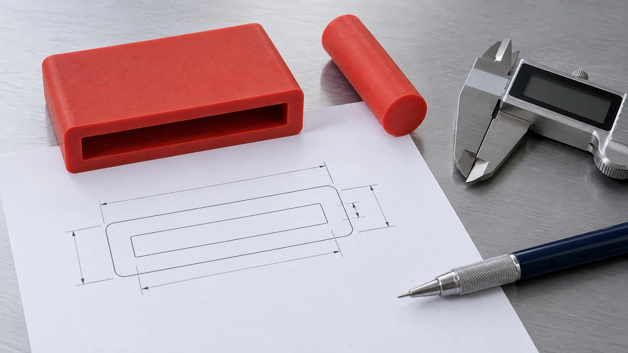
A technical drawing for custom silicone profile manufacturing should show more than the part's shape. Clear dimensions, material requirements and installation conditions make the assessment easier. You can start with a drawing or share measurements and photos describing your existing sample.
Prepare a clear cross-section drawing
In extrusion, material is passed through a die to form a continuous cross-section and then cured. The profile's cross-sectional geometry is therefore one of the key inputs for production assessment. Alongside the overall width and height, the drawing should clearly show internal cavities, walls, channel openings and any required corner details.
- Show the outer boundaries of the cross-section and any internal cavities.
- State the measurement unit clearly, for example mm.
- Specify key dimensions without duplication or contradictions.
- Mark important contact surfaces and the mating component.
- Include the existing profile number, if available.
Distinguish nominal dimensions from tolerances
The nominal dimension is the target dimension. The tolerance defines the accepted range of variation for that dimension. Identify dimensions that are particularly important for fit, contact or closing. Rather than applying the same precision to every dimension, explain which dimensions are critical to your application.
Bear in mind that an existing sample may be deformed or its dimensions may have changed during use. Share both sample measurements and the equipment's mating dimensions to clarify the target cross-section for new production.
Add material and production requirements
| Information | Details to include in the enquiry |
|---|---|
| Material | Hardness scale and value, colour, required compliance information |
| Operating conditions | Temperature and duration, pressure / vacuum, contact substances and cleaning agents |
| Installation | Channel or mating component, contact direction, corners and joints |
| Production | Length / metres, quantity and cutting requirements |
This information is used together for technical review and quotation. If any detail in your drawing has not been finalised, say so; let's clarify it during the assessment rather than leaving it as an assumption.
Short answers about drawing preparation
Is a DXF or DWG file sufficient on its own?
Include the measurement unit, critical tolerances, material and application description with the file. Having this information clearly stated is as important to the assessment as understanding the geometry.
How can I start without a drawing?
You can share the sample's cross-section, key dimensions and installation photos. Cross-section examples and installation checks help you see what information to prepare.
Final checks before sharing a file
A dimensioned PDF makes the drawing easier to read. You can also use a DWG or DXF file if you have one. JPG, PNG and WebP are supported for application photos. You can attach one file of up to 20 MB to the website enquiry form.
Check that the file is the current version, the dimensions are readable and it is consistent with the technical description. Send your technical drawing; let's assess your cross-section, dimensions and production requirements together.