
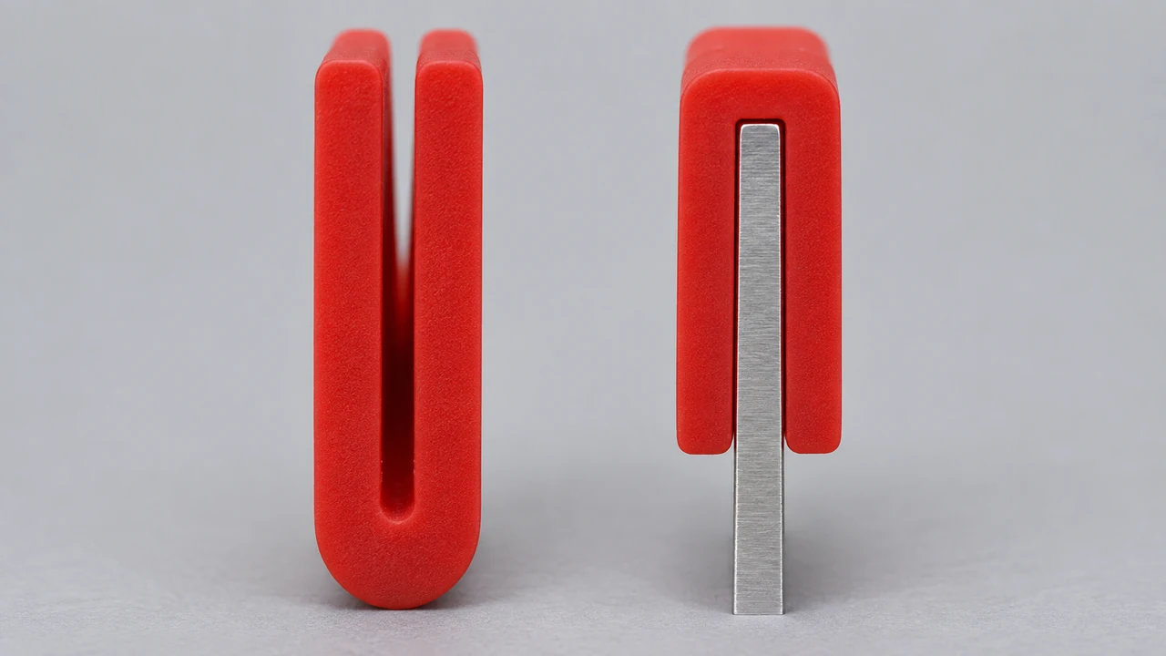
The open side of a U-channel silicone profile is assessed together with the mating component inside it. For a profile fitted over a metal edge or seated in a channel, knowing only its outer dimensions is not enough. The internal opening and mating component's cross-section are key to the fit.
Consider the three dimensions together
- Mating component thickness: The dimension of the sheet metal or edge the profile will surround.
- Channel opening: The internal distance across the profile's open section.
- Seating depth: The distance the mating component will sit inside the profile.
The data sheet for U-channel profile 21720 shows nominal outer dimensions of 4 × 9,5 mm, a channel opening of 1 mm and an internal channel depth of 7,5 mm. These values define the profile cross-section. Suitability for a particular metal edge is determined separately using mating dimensions, tolerances and operating conditions.
Check the mounting surface
Assess burrs, sharp edges and surface irregularities on the mating component. Identify any areas that could strain the profile's inner surface before installation. When sharing a sample or photo, show not only the metal thickness, but also its edge shape and any corner turns.
Forcing the profile into place is not a valid way to check whether the internal opening is suitable. Assess channel dimensions, component placement and required installation conditions together; specify any fixing or adhesive requirements for the particular application.
Check the cross-section along the installation
The profile should sit consistently along the mounting surface. A correct appearance at one end alone does not confirm fit over the full length. Corners, joints, bends and end details need to be checked.
- Are the profile and metal edge aligned in the correct direction?
- Are both side walls positioned evenly?
- Are there visible gaps or signs of strain along the seating area?
- Does the position change at corners and joints?
- How does the mating component's movement or closing action affect the profile?
Short answers about U-channel installation
Will a 1 mm channel opening definitely fit every 1 mm metal edge?
Nominal dimensions alone do not confirm fit. The profile and mating component tolerances, edge shape and installation conditions are considered together.
Which photos are most useful for an enquiry?
The empty profile cross-section, metal edge and installation viewed from different angles are useful together. Profile selection requires cross-section information; a technical drawing requires key dimensions.
Prepare an enquiry that explains the installation
Share a dimensioned cross-section drawing, a photo of the empty profile and a view after installation together. The metal edge and U profile in the image are illustrative examples of the basic fitting arrangement; they do not show the dimensions of your application.
View the visual installation guide. Send your mating component dimensions and application photo; let's confirm the suitable cross-section and installation details together.